Dave Spencer's Hobby Electronics Web pages
© 2017 David E. Spencer
Prototyping
The planning and building of "one-off" circuits is a most important part of hobby electronics - it's
certainly the part that's the most fun!.
There are several ways of building prototype circuits on a variety of "platforms". Some are better suited to different
types of circuits than others and we all have our own preferred methods. The list below is not fully comprehensive but I
have tried all of them.
Some notable exceptions are the production of one-off printed circuit boards and SMD ("surface mounted devices") technology.
Ready made products using these technologies using ready made printed circuit boards and assembled SMD boards have an important place in hobby electronics but they are
much better bought as the result of an expert's efforts rather than suffer the high failure rate of learning these technologies.
"Solderless Breadboards"
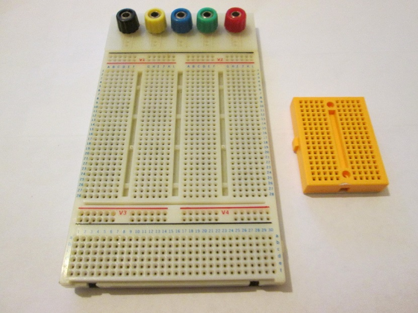
Most circuit ideas will first see the light of day on a solderless breadboard. Component leads are
pushed into the holes on the board which are arranged in linked rows to allow components to be connected to each other.
the layout is best seen in the next image of a solderable breadboard whose layout is almost the same as the solderless board.
Breadboards come in a range of sizes, layout and connectability. The two above are examples to
illustrate the variety.
"Powering Solderless Breadboard circuits"
The simplest way to provide power to a cicuit on a breadboad is to use the side rails as power rails connected to
a 3.3v, 5v, 9v source such as a battery or a suitable power supply. However slightly more elegant solutions are available. These are boards
plugged into the power rails of the board, inputting a convenient supply voltage and outputting a regulated voltage to the circuit. These are
nowadays marketed with 3.3v and 5v output options. An example is shown below:
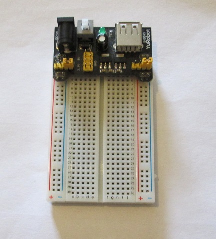
This example has a choice of 3.v or 5v supply voltages selected by the jumpers. Input can either be via a USB connection or a standard
power socket from a "Wall wart". What limits their usefulness is that breadboards come in many more widths than those offered by the manufacturers of the little
supply boards. I find myself with several breadboards that did not fit any of the manufactured boards. The simple answer was to build my own limited version
like this one:
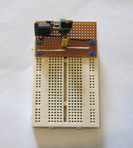
This one is built on a scrap of stripboard. The width is adjusted to fit the breadboard. There are two output voltages - one is
the same as the input from the power supply (9v in this case) and a regulated 5v output from a 7805 voltage regulator integrated circuit. The output could be changed, for
example to 3.3v by using a 3.3v instead of a 5v regulator.
"Solderable Bread boards"
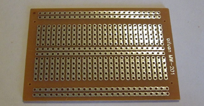
To make your new circuit idea more permanent it needs to be soldered into its final form.
I only discovered these boards relatively recently. Simply transfer the components from your breadboard layout
one component at a time and solder them onto the board.
Compared to most of the other boards on this page the solderable breadboards are not especially
cheap but googling "solderable breadboard" can get you some at a better price. I got mine from a supplier on Ebay and I've been very pleased with
them.
"Point to point wiring"
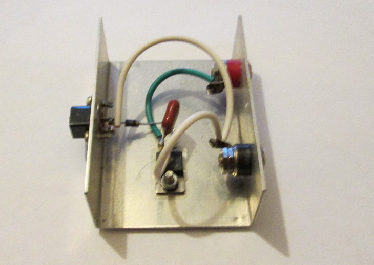
Point to point wiring is electronics at its most basic but for most circuits there are much more robust
construction techniques. Components are simply soldered to each other. One situation where point to point wiring is useful is when the compoents are all
mounted in an enclosure of some kind - the components are joined directly to each other or using wires.
the example below is a power supply which takes an input of a DC supply of 15 volts or more and outputs a
reliable 12v. The component list is simple - an input connector, two output connectors, a 7812 voltage regulator, a capacitor and a diode. The most expensive
item is the enclosure.
Circuits built on Tag Strip

A way of using the ideas of pont to pont wiring in a more structured format is provided by tag strips.
Tag strips are connectors with more than one connecting lug lined up on a base of insulator such as paxolin.
Tag strips have a history of use in bespoke military circuits - they can provide a rugged circuit environment. Single
components can easily be tested and replaced if identified as defective. They have long been popular with model railway enthusiasts
but in recent years tag strip is relatively expensive and can be hard to find. "Googling" using "Tag strip" as a search
term will bring up some suppliers and different styles of tag strip.

This is a slightly different pattern of tag strip -
there are a few other variations on the basic idea.
Circuits built on terminal strip
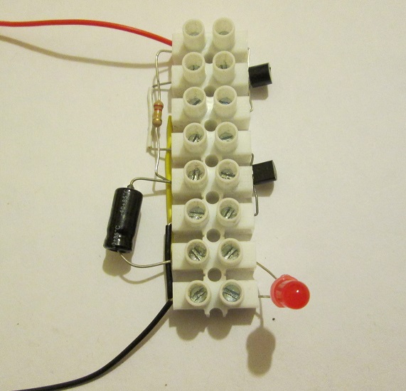
The image on the left is of a 2-transistor astable cicuit used to flash a LED.
This is a very similar method of building circuits to the tag strip method. Indeed
component layouts are identical for both methods. All components are recyclable and interchangeable between the two methods whilst terminal block strip is much
cheaper than tag strip. Back in the early 1970's before solderless
breadboards became cheap and easily available many science teachers including me used terminal block strips as a means of
solderless construction of some simple circuits. The main drawback is that the layout of components does not resemble the appearance of a conventional circuit diagram or schematic and
sometimes a certain amount of ingenuity is needed.
If you are interested in building circuits in this way then a very useful book written in
1995 is still currently (2017) available at moderate cost.The book is Roy Bebbington's "45 simple electronic terminal
block projects. The publisher is Babani and the book has the publisher's number of BP378. The ISBN number is 085934-378-2. Roy Bebbington did write a sequel
called "30 simple IC Terminal Block Projects". Also by Babani its ISBN is 085934-379-0.
Circuits built on perforated circuit board ("perfboard")
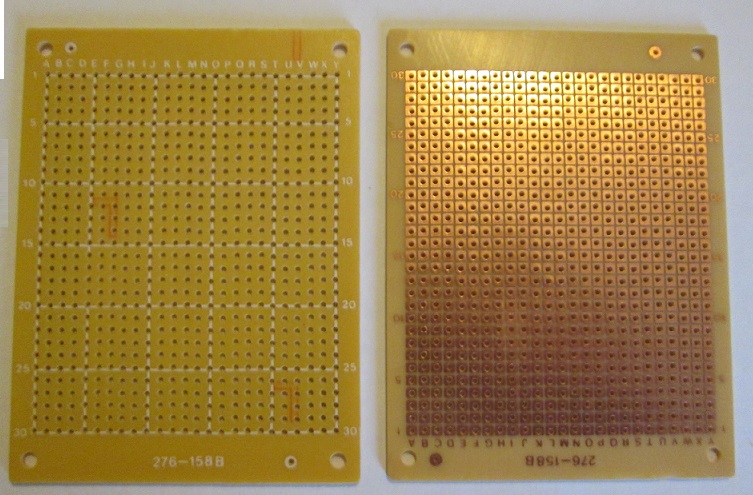
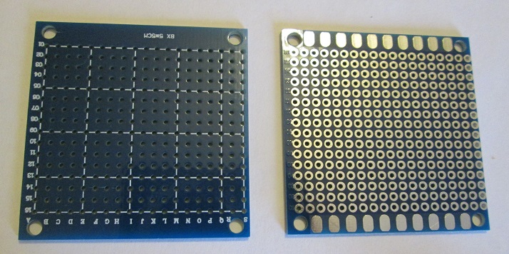
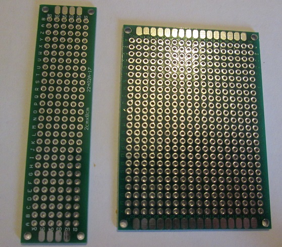
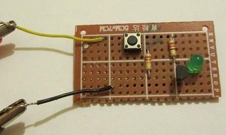
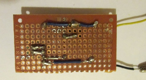
These two images are of the top and bottom of the fragment of perf board that was my first attempt at this method of prototyping. I have used some Kynar wire connection, some solder bridging
and using a component wire as a connector. All it does is switch on a LED through a single transistor.
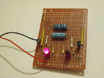
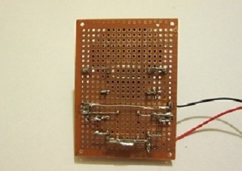
This is a later attempt to build a two transistor astable circuit to alternately flash two LED's.
The connecting wiring on the back is done using solder bridges and component leads. This was an early attempt at this method.
Once you start to get the hang of it it's not too bad.
For many constructors it is possible to avoid the use of perfboards altogether - I managed for
years with stripboard for many projects. However if you decide to start using devices such as the Raspberry Pi and the
Arduino and you want to build bespoke breakout devices and boards then you inevitably find that you need to be able to
build functional circuits on perfboard.
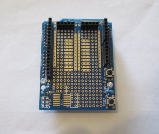
This is a "shield" for an Arduino used as a breakout board.
The shield sits on top of the main Arduino board. Any circuitry needed for the breakout device
is built on the perfboard.Note that there are buses (multi-access points) within the layout of the shield.
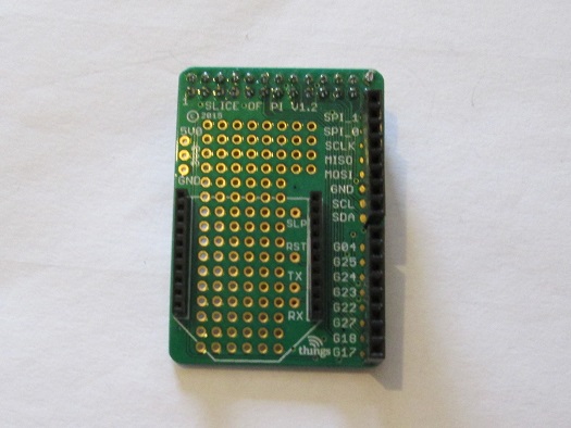
This is a "shield" for a breakout board but this one is for a Raspberry Pi.
Unlike the Arduino the shield is connected to the main Pi board using a multi-stranded cable and connector.
Any circuitry needed for the breakout device
is built on the perfboard. Note that there are no buses within the layout of the shield.
Circuits built on stripboard
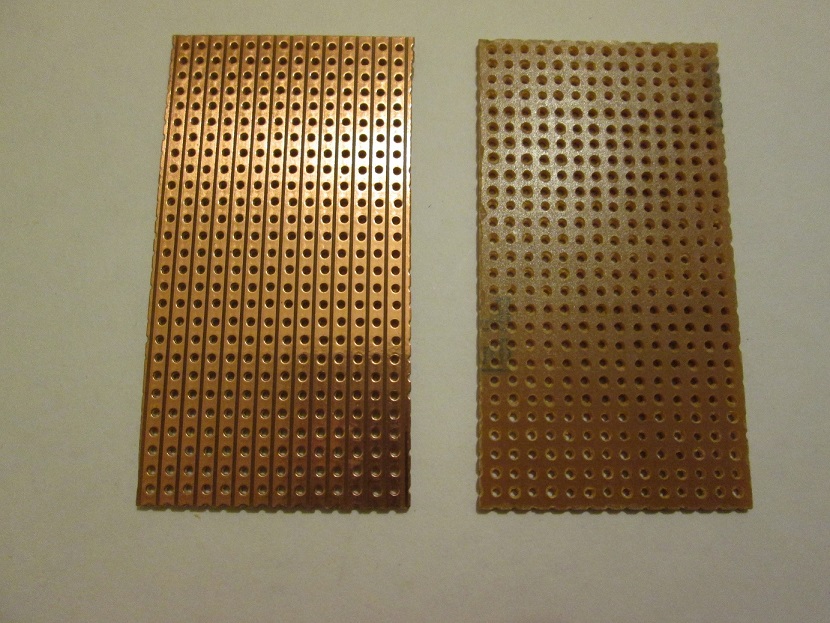
Stripboard consists of a perforated board on which strips ("tracks") of copper connector link the holes in lines.
Breaks in the track can be made using a special cutter or a small drill bit for metal cutting. This does impose design
limitations and some ingenuity can be useful. However whole books of stripboard designs have been published and the technique remains popular with
beginners. Some authorities discourage the use of stripboard because of its design limitations but as a personal view I still tend to prototype using
this method unless one of the others really is an obviously better way. Note that there are many generic makers of stripboard but there is a brand leader,
Veroboard, which is often used to describe striboard generally. I do have to say that I like genuine Veroboard.
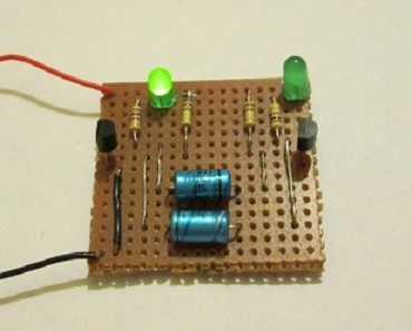
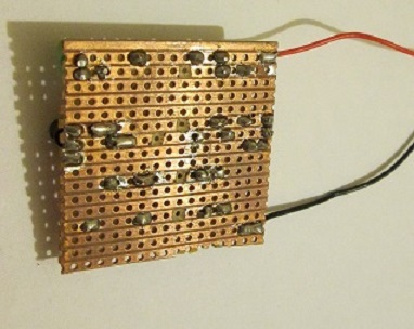
This is a very early attempt to build a two transistor astable circuit to alternately flash two LED's on stripboard. Although some of the detail is clumsy
it does illustrate the breaking of tracks.
Circuits built on PerfBoards with buses
There has been a lot of debate as to how best to design your prototypes - stripboard or perfboard?.
Both have their advantanges and limitations. However there are boards on the market at reasonable cost which offer
the best of both worlds. These are the perfboards where each pad ("bus") allows several separate connections to be made
at a specific location in the circuit. I'm more and more becoming a fan of these low cost boards. They lend themselves
(sometimes with minor adaptations) to circuits of buses linked by voltage supply and ground tracks.
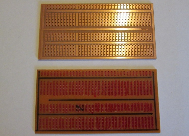
This type of board is rapidly becoming my favourite!. The lower part of the image shows the
topside of the board where I have marked the buses in red and the (single) track in black. Cutting this track into two at the
bottom left hand corner allows creation of "positive" and "negative" tracks. from here on in with some careful planning some
quite sophisticated circuits can be built.
As a practical tip I have found that connecting a bus to a track by means of a solder bridge is unreliable
and tricky. I use a short length of wire soldered to the bus on the soldered side of the board then solder the wire to the track.
This works extremely well.
On the topside of this particular board I drew out the busses and tracks with res and black fine marker pens.
This can make circuit layout planning much easier and (hopefully!) more foolproof.
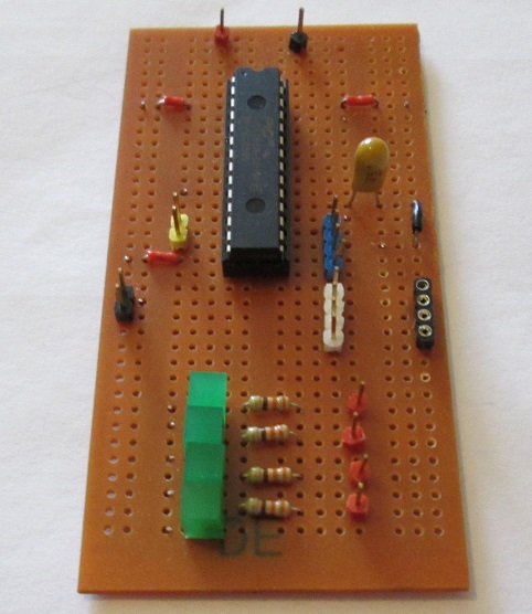
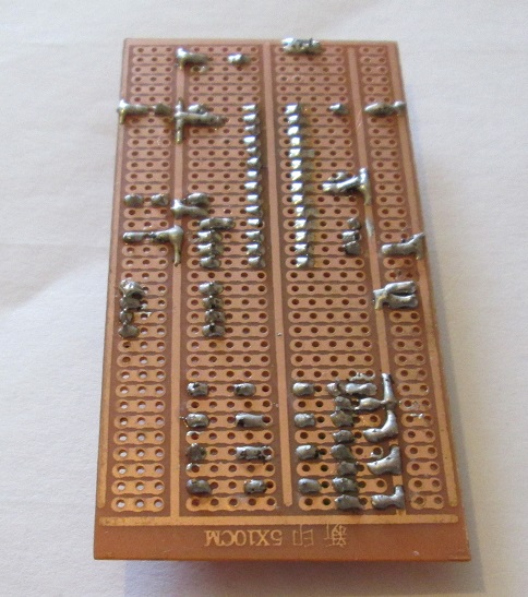
This is a homemade development board for a Micromite microcontroller that I built on one
of the above boards. On the image of the underside on the right note how I have connected the buses to the power
tracks. This is not the only way it can be done but I find that it suits me.
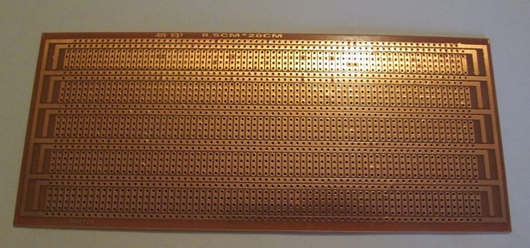
This board is the big brother of the last. It is much larger and the track and bus layout is different but the general
idea is the same. I have to confess that I have not yet built a prototype that could not be built on the smaller board but at the price these
came at I though it was worth buying them in case I needed one and did not want to wait until they got here from China or Hong Kong.
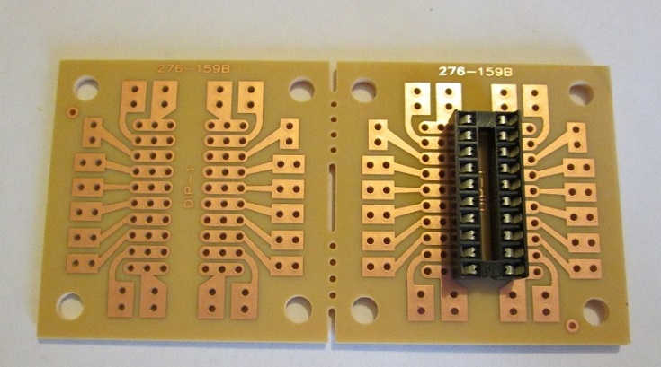
This is a pair of boards, each of which has a 20pin DIL socket soldered onto it. Each of the 20 pins has a bus or pair of buses
to connect components to the IC (or IC's) plugged into the DIL socket. It is possible to have two separate circuits on the same board. A very uuseful bit
of kit only recently discovered by me on Ebay.
Circuits built on Printed circuit boards (PCB's)
Strictly speaking, unless you are going to go down the road of designing a circuit, convert this to a
viable PCB layout then go through the process of etching a bespoke PCB then what follows is not strictly "protoyping". It is,
however, possible to find a ready-made PCB which does the job you want then there are so many ready-made PCB's about often at
bargain prices then I feel "Why not?!". With many of these kits it is possible to alter some component values - this surely comes within the
prototyping "umbrella".
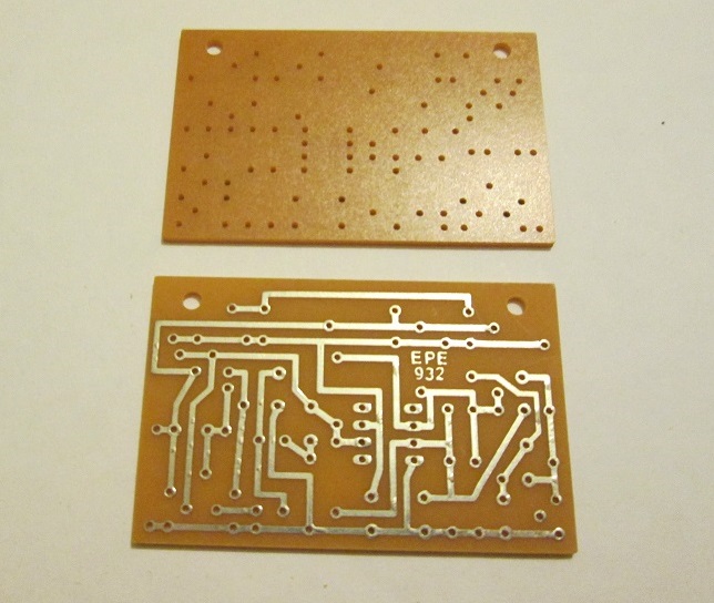
This is an old fashioned PCB in that it has a system of visible tracks, very much like a bespoke PCB.
It was a very useful giveaway some years ago by the magazine "EPE" ("Everyday and practical electronics") as a multi-purpose pcb for which they published
several suggested circuit ideas. I remember buying several copies of the magazine to get the freebie PCB's. They are easy to build on and you do generally (if your soldering's OK)
get the result you want.
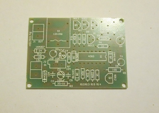
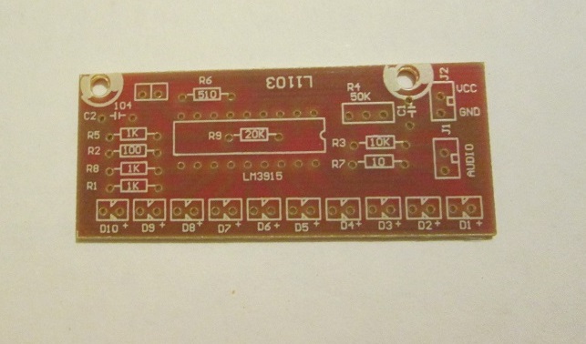
The next two PBC's are from PCB board + components kits which can be bought very cheaply from online
sources such as Ebay. The component locations and values are clearly marked and assembly is generally straightforward. Kits
like this are a very good way of learning to solder components to make a working circuit.
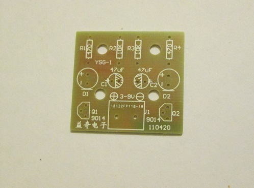
This is a little board that can be bought on its own or with the components as a kit incredibly cheaply.
On it you build a two transistor astable and use this to alternately flash two LED's.
My only moan about this particular board is that the transistors used have an unusual pinout. Rather than try to substitute
transistors with a similar pinout I found it easier to track down some of the relevant transistors and buy a few of them.
Alternatively buy the board + components kits.
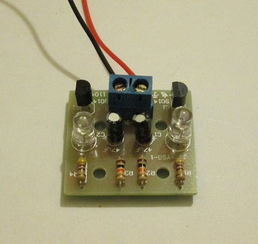
This is one of the above boards with all components soldered into place.
Return to Hobby Electronics Home page
Return to Hobby Electronics Index page
Return to Dave Spencer's Web pages


